Metering, Integration, Analytics
Energy & Water Metering Products
0

PAN-14 Sensor installation, operation and maintenance manual

Overview

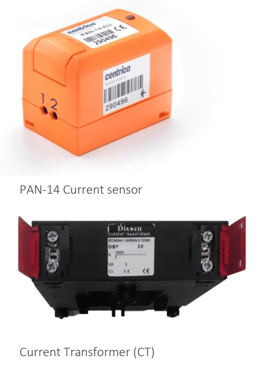
This user guide explains how to install the PAN-14 sensors which works in conjunction with an external 0-5 Amp secondary current transformer (CT). 

Workflow

Sensor installation consists of the following steps: 

  1. Map the circuits. See Panoramic Power deployment guide. 
  2. Physically attach the sensors and the CTs to the wires. 
  3. Monitor the proper functioning of the sensors. See Panoramic Power deployment guide. 

Unpacking the hardware
Sensors are shipped in 3-unit packs.
CTs are not included and can be bought separately.

Safety precautions 
The sensor must be installed only on an insulated conductor. CTs output/secondary current must not exceed 5A. The sensor and CT should be installed and removed only by a qualified electrician. 

Installation must not be performed on a live wire for reasons of safety and random shock hazard. Power supply to the panel must be shut off before and during installation. 

The sensor and CT must not be installed lying or touching bus bars or any other non-insulated, exposed conductors. 

Installation is possible both on external entry/exit conductors before the terminal strip, as well as both ends of the circuit breaker. The least cramped, most accessible location should be chosen for installation. The sensor should be installed such that the arrow points in the direction of the load. 

Caution Protection provided by the equipment can be impaired if used in a manner not specified by the manufacturer. 

Installing the sensor

PAN-14 and the associated current transformer should be installed in a location not accessible to an average user. The voltage and current measurement circuit insulation should be adequate for 300V, CAT III, double/reinforced insulation from mains.

This procedure must be carried out by a certified electrician.

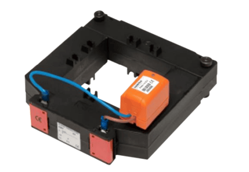
  1. Connect the PAN-14 sensor to the CT by connecting the two CT’s outputs to the PAN-14 sensor using 1.0-4.0mm2 (12-17 AWG) wires, as follows:

a. Connect the PAN-14 sensor’s terminal marked as ‘1’ to the CT’s terminal marked as ‘S1’ or ‘X1’
b. Connect the PAN-14 sensor’s terminal marked as ‘2’ to the CT’s terminal marked as ‘S2’ or ‘X2’

Caution A lose CT connection can become a fire hazard. When connecting the unit to the CT make sure that both CT wires are properly inserted and that the screws are well tightened.

 2. Mount the CT on the hot wire: 

a. If the CT is split-core: 
Close the CT on the hot wire by disconnecting its two parts and closing them around the hot wire. 

b. If the CT is solid -core: 
Disconnect one of the ends of the hot wire from the panel, insert it through the CT, and then reconnect it to the panel. 

c. In both cases, make sure the CT is placed on the wire so that the direction of current flow on the wire is from the side marked ‘P1’ or ‘H1’ on the CT, to the side marked ‘P2’ or ‘H2’ on the CT. Other used CT polarity markings are K for entry and L for exit or Load Side (respectively P1 and P2). 

4. Finalize the PAN-14 sensor and the CT’s position on the panel: 


a. Maintain a reasonable distance between the CT and the sensor. 


b. Place the PAN-14 sensor on the side that is closer to the bridge (to avoid RF blocking, make sure the CT is not positioned between the sensor and the bridge). 


Caution Do not hang the PAN-14 sensor from the CT, as the connection cannot withstand the sensor weight and can become a fire hazard. Make sure that the sensor is properly mounted, for example using plastic ties.


Important notes 


  • Do not mount the CT on the hot wire before you have already connected the PAN-14 sensor securely to the CT! 
  • If a PAN-14 sensor needs to be replaced, short circuit the CT’s outputs to each other using a length of wire before PAN-14 is disconnected! 
  • Do not leave the CT mounted/installed on a hot wire without being short circuited.
  • It is possible to have both the PAN-14 sensor and the short-circuiting wire connected to the CT at the same time (but PAN-14 will not measure current accurately while the short-circuiting wire is connected).


Registering the installed sensor 


See Panoramic Power deployment guide. 


Monitoring sensor activity 


See Panoramic Power deployment guide. 


Uninstalling a sensor 


Open the sensor in the way you first opened it and remove it from the cable.

Items have been added to cart.
One or more items could not be added to cart due to certain restrictions.
Added to cart
- There was an error adding to cart. Please try again.
Quantity updated
- An error occurred. Please try again later.
Deleted from cart
- Can't delete this product from the cart at the moment. Please try again later.