
PAN-42 Sensor installation guide
Overview

The PAN-42 wireless power sensor provides high-accuracy real-time power and power quality measurements for mains power monitoring, sub-metering and metering of large loads.
Designed for demanding electrical applications, supporting industry accuracy standards, PAN-42 enables the metering of power, voltage, current, power factor and power quality measurement data.
Information is sent wirelessly, through Panoramic Power’s Bridge unit, to Panoramic Power’s advanced cloud-based analytics platform. The data is then used to provide customers with actionable analytics and real-time dashboards and alerts.
Workflow
Sensor installation consists of the following steps:
- Map the circuits. See Panoramic Power deployment guide.
- Physically attach the sensors and the CTs to the wires.
- Monitors the proper functioning of the sensors. See Panoramic Power deployment guide
Safety precautions
Read the instructions in this manual before installing, and take note of the following precautions:
• Ensure that all incoming AC power and other power sources are turned off before performing any work or connecting the PAN-42. Failure to do so may result in serious or even fatal injury and/or equipment damage.
• Under no circumstances should PAN-42 be connected to a power source if it is damaged.
• To prevent potential fire or shock hazard, do not expose PAN-42 to rain or moisture.
• Ensure that the external current transformers are shorted (by using the recommended shorting switches) before disconnecting PAN-42 from its current inputs.
The sensor and CTs should be installed and removed only by a qualified electrician. Read this manual thoroughly before connecting the device to the current-carrying circuits.
During operation of the device, hazardous voltages are present on input terminals. Failure to observe precautions can result in serious or even fatal injury, or damage to equipment.
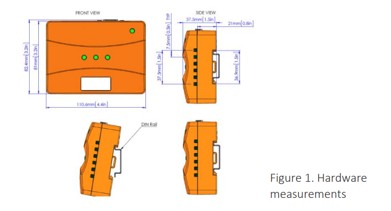
Mechanical installation
There are several mounting options for PAN-42:
- On a 35-mm DIN rail (see the drawing below)
- By using screws, using the slots on the back of the device
- With plastic tie-wraps, using the hooks on the back of the device
Electrical connections
PAN-42 supports the following phase configurations:
1. Single-phase – 120VAC (US) or 230VAC (EU) phase-neutral
Supported voltage range: 110-277 VAC phase-neutral
In this configuration, the single voltage line (phase and neutral) should be connected to L1 & N, and a single CT should be connected to I1.
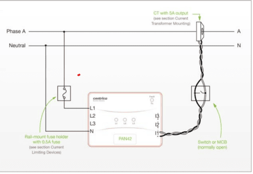
Single-phase configuration
2. Dual-phase – 240VAC (US) phase-phase
Supported voltage range: 220-554VAC phase-phase
In this configuration, the two voltage lines (phase A, phase B, and neutral) should be connected to L1, L2 & N, and two CTs should be connected to I1 & I2.
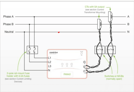
Dual-phase configuration
3. 3-phase 4-wire (wye) – 120/208VAC (US), 277/480VAC (US), or 230/380VAC (EU)
Supported voltage range: 110-277VAC phase-neutral / 190-480VAC phase-phase
In this configuration, all three voltage lines & neutral should be connected to L1, L2, L3 & N, and three CTs should be connected to I1, I2 & I3.
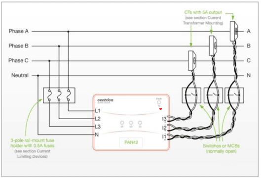
3-phase 4-wire (wye) configuration
4. 3-phase 3-wire (delta) – 120/208VAC (US), 277/480VAC (US), or 230/380VAC (EU)
Supported voltage range: 110-277VAC phase-neutral / 190-480VAC phase-phase
In this configuration, all three voltage lines should be connected to L1, L2 & L3 (N is left open), and three CTs should be connected to I1, I2 & I3.
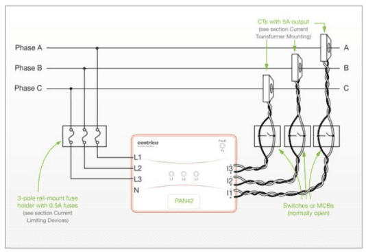
3-phase 3-wire (delta) configuration
5. 3-phase 4-wire (wye) – 346/600VAC (Canada)
Since this voltage is beyond the rated voltage range of PAN-42, potential transformers must be used on each of the three voltage inputs. The PTs’ primary windings should be connected between each phase and neutral, and the secondary windings should be connected to L1, L2, L3 & N. Three CTs should be connected to I1, I2 & I3.
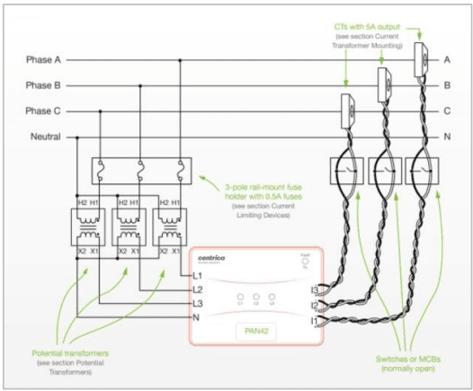
3-phase 4-wire (wye) 346/600VAC configuration
6. 3-phase 3-wire (delta) – 346/600VAC (Canada)
Since this voltage is beyond the rated voltage range of PAN-42, potential transformers must be used on each of the three voltage inputs. The PTs’ primary windings should be connected between each phase and a common connection point (virtual neutral), and the secondary windings should be connected to L1, L2, L3 & N. Three CTs should be connected to I1, I2 & I3.
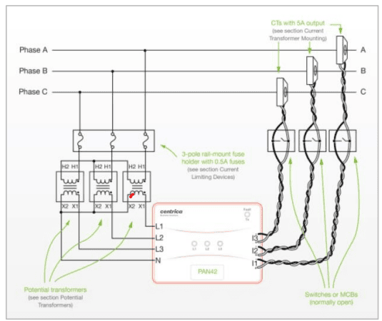
3-phase 3-wire (delta) 346/600VAC configuration
Note PAN-42 does not support a 3-phase high-leg delta configuration.
Important notes
1. Voltage lines must be connected through a current-limiting device. Current protection should be maximum 1A per phase. It is advised to use in-line rail-mount fuse holders. See the Current Limiting Devices section for recommended devices and specifications.
2. Ground wires should not be connected to any of PAN-42’s voltage inputs, (including the Neutral input).
3. The gauge of the voltage input wires (between the current-limiting device and PAN-42) must be 0.8-4.0mm2 (12-18 AWG).
4. Wrong polarity of the current transformers (CTs) will result in incorrect readings. See the ‘Current transformer mounting’ section for more details.
5. Never leave a CT’s output open while primary current is flowing. If you need to disconnect the sensor from a CT, short its output (secondary winding) using its shorting switch, as shown in the connection diagrams above. The shorting switch is optional but not mandatory when using traditional split core CTs. For deployments that utilize Rope CTs (Rogowski coil) it is strictly prohibited to use a shorting switch.
6. When connecting to mains voltage >277VAC phase-neutral, or when installing in a noisy industrial environment, a potential transformer is required. See the ‘Potential transformers’ section for more details.
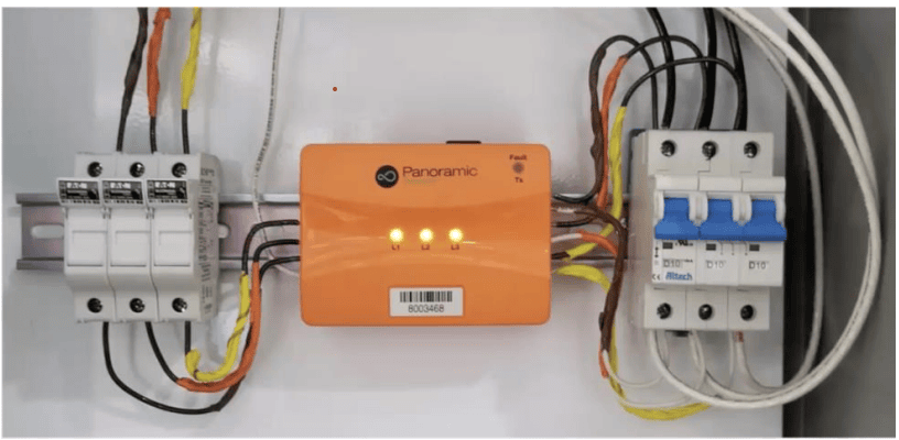
PAN 42 installed on a DIN rail
Mapping the site
See Panoramic Power deployment guide.
Current transformer mounting
Polarity Current transformers (CTs) have polarity, and must be installed in the correct direction. This is important on both sides of the CTs:
1. The CTs must be placed on the load wires (primary side) so that current flows as shown by the arrow marked on the CT, or by the following common markings:
a. From the side marked ‘P1’ to the side marked ‘P2’
b. From the side marked ‘K’ to the side marked ‘L’
c. From the side marked ‘H1’ to the side marked ‘H2’
2. The CTs’ outputs (secondary side) must be connected to PAN-42’s current input terminals as indicated by the following common markings:
a. Terminal or wire marked ‘S1’ to current terminal marked ‘+’ on PAN-42, and ‘S2’ to ‘–‘
b. Terminal or wire marked ‘K’ to current terminal marked ‘+’ on PAN-42, and ‘L’ to ‘–‘
c. Terminal or wire marked ‘X1’ to current terminal marked ‘+’ on PAN-42, and ‘X2’ to ‘–‘
Output shorting
As shown in the ‘Electrical connections’ section above, the CTs should be connected to PAN-42 through normally-open shorting switches or MCBs. Before mounting any CT on an active hot wire, its switch/MCB should be switched to the closed position, so that the CT’s output is shorted. After the PAN-42 sensor’s current input is connected, the switch can be moved to the open position.
Failure to short a CT’s output when it is placed on an active hot wire can cause irreparable damage to the CT!
Connection wires to PAN-42
The CTs’ secondary outputs are connected to the PAN-42 sensor’s current input terminals. The wires used to connect the CTs to PAN-42 (through shorting switches) should have the following characteristics:
1. Gauge: 0.5-4.0mm2 (12-20 AWG)
2. Maximum length: depends on gauge – voltage drop across the wires’ total length must not exceed the CT’s specification at 5A of current. The following list shows maximum lengths (per wire, total length between CT and PAN-42) for some common wire gauges:
a. 1 mm2 – 1.5 m
b. 0.5 mm2– 75 cm
c. 16 AWG – 6 feet
d. 18 AWG – 4 feet
e. 20 AWG – 2.5 feet
3. Twist ratio: one twist per 5mm (2 inches)
Installing the sensor
This procedure must be carried out by a certified electrician.
1. Make sure the CT outputs are shorted (see the ‘Current transformer mounting’ section above)
2. Mount the CT(s) on the hot wire(s):
a. If the CT is split-core: Open the CT, and close it around the hot wire.
b. If the CT is solid-core: disconnect one of the ends of the hot wire from the panel, insert it through the CT, and then reconnect it to the panel.
c. In both cases, make sure the CT is placed on the wire so that the direction of current flow on the wire is correct (see the ‘Current transformer mounting’ section above). ‘
3. Connect the CT(s) from one to three phases A, B, C to the PAN-42 sensor’s current input terminals marked ‘I1’, ‘I2’, ‘I3’, respectively, making sure polarity is correct, and wire gauge and length are appropriate (see the ‘Current transformer mounting’ section above).
4. Connect the voltage inputs:
a. Connect one to three phases A, B, C to the PAN-42 sensor’s voltage input terminals marked ‘L1’, ‘L2’, ‘L3’, respectively. If there is a neutral wire, connect it to the ‘N’ terminal. Refer to the Electrical Connections section above for more details about connecting different phase configurations.
b. Make sure each phase is connected through a current limiting device (see the ‘Current limiting devices’ section for details).
c. If the phase voltages are higher than the rated input of PAN-42, such as 346/600V systems in Canada, connect the phases through potential transformers, as shown in the ‘Electrical connections’ section (see also the ‘Potential transformers’ section for more details). In this case, make sure that you measure the input and output voltage of each potential transformer, and record the input to output voltage ratio for use in the deployment process (the potential transformer’s rated ratio is often not completely accurate, and so the voltages must be measured).
d. Make sure that you use the same phase for the current and voltage inputs; that is, L1 and I1 are for the same phase, L2 goes with I2, and L3 goes with I3.
e. Note In order for the PAN-42 sensor to turn on, the neutral wire and at least one voltage phase, or at least two voltage phases, must be connected.
5. After connecting the current and voltage inputs, make sure that the phase indication LED for each phase connected is steady green, and that the Tx LED flashes green every 10 seconds.
6. For each phase, the LED indications are as follows:
Connection LED visual indication
Both voltage1 and current2 are connected Steady green
Only voltage is connected Flashing green
Current connection is reversed Flashing orange
Only current2 is connected Flashing red
No voltage1 or current2 is connected Off 1
7. Finalize the PAN-42 sensor’s and the CTs’ position in the panel, maintaining a reasonable distance between the CTs and PAN-42.
Important notes
Do not mount the CT on the hot wire before you have already connected its outputs to the PAN-42 sensor, or to the shorting switch, making sure the switch is in its closed state!
If a PAN-42 sensor needs to be replaced, put the suggested shorting switches in their closed states before PAN-42 is disconnected!
Do not leave the CT mounted/installed on a hot wire without being short circuited.
Resetting the internal energy counter
PAN-42 holds an internal, nonvolatile energy counter that keeps the accumulated energy (kWh) readings. It is recommended to reset the counter when installing a new PAN-42 unit. To reset the counter, insert a pin into the hole on the back side of PAN-42, press and hold the pin for 5-8 seconds. When the resetting is complete, the three phase-indication LEDs will flash once in red.
Registering the installed sensor
See Panoramic Power deployment guide.
Monitoring sensor activity
See Panoramic Power deployment guide.
Uninstalling a sensor
Put the in-line fuse holders on the phase lines in their open position, thereby disconnecting the voltage inputs from the PAN-42 sensor. Put the CT shorting switches in their closed position. Then disconnect the current and voltage inputs from the PAN-42 sensor and remove it from the electrical panel.
Current limiting devices
For each voltage phase connected to the PAN-42 sensor, a current-limiting device must be connected in series. Modular rail-mount fuse holders are recommended.
For installations with more than one phase, one multiple-phase fuse holder should be used, so that all phases are disconnected at once when the fuse holder is put in the open position.
The neutral wire should not be connected through a current-limiting device.
The following are recommended fuse holders:
• Littelfuse LPSC series (LPSC0001Z for 1 phase, LPSC0002Z for 2 phases, LPSC0003Z for 3 phases)
• Cooper Bussman CHCC series (CHCC1DU for 1 phase, CHCC2DU for 2 phases, CHCC3DU for 3 phases)
• Fuses used should not exceed 1A rating.
• The following are recommended fuses (0.5A):
• Littlefuse KLKR.500
• Edison HCLR0.5
Potential transformers
When connecting the PAN-42 sensor to a panel with phase-neutral voltages over 277VAC (such as 346/600VAC systems in Canada), it is necessary to use potential transformers (PTs) at the voltage inputs (see the ‘Electrical connections’ section above for connection diagrams).
PTs must be chosen so that their output (secondary) voltage is always within PAN-42’s input voltage range (110-277VAC phase-neutral). It is recommended to use PTs with high voltage accuracy and minimal phase shift, in order to minimize the effect on PAN-42 measurement accuracy.
For Canadian 346/600VAC systems, it is recommended to use PTs with 346VAC inputs and 120VAC outputs, such as the following models:
• Instrument Transformers (ITI/GE) model 3VT468-346 (3-phase)
• Hammond Manufacturing model VT56A (1-phase)
• For noisy industrial environments, where voltage spikes are common: Hammond Power Solutions model PH50MGJ (1-phase) – connect to 380V input, 120V output
Note The above PTs are recommended for use with the PAN-42 sensor, but they are not considered a part of the PAN-42 product, and Panoramic Power does not take responsibility for their certification status or suitability to the installation site.