
PAN-10-063 and PAN-12-225 Sensor Installation Manual
Overview
The Panoramic Power System monitors electrical energy consumption at individual circuit level and detects excess usage allowing organizations to identify and reduce energy and maintenance expenses. The Panoramic Power System consists of wireless, self-powered sensors engineered to allow for rapid, non-invasive installation, with almost no disturbance to operations. Sensors are easily attached to circuit breakers by just snapping them on to the outgoing electrical wire. They monitor the flow of electricity through the resulting magnetic field and also use the field as a power source. The sensors do not require any maintenance. Data collected by the sensors is sent to a bridge, which, in turn, transfers the information to the Panoramic Power System server through the Internet, using Cloud technology. The sensors report the energy consumption to the bridge at sub-minute intervals. Consumption reports can be retrieved through the system. This user guide explains how to install the sensors.
Workflow
PAN-10 and PAN-12 Sensor installation consists of the following steps:
- Map the circuits. See ‘Panoramic Power deployment tool user guide’.
- Physically attach the sensors to the wires (this guide).
- Monitors the proper functioning of the sensors. See ‘Panoramic Power deployment tool user guide’.
- The sensor must be installed only on an insulated conductor.
- The conductor’s diameter and maximum current must match the specification printed on the sensor.
- The sensor should be installed and removed only by a qualified electrician.
- Installation must not be performed on a live wire for reasons of safety and random shock hazard. Power supply to the panel must be shut off before and during installation.
- The sensor must not be installed lying or touching bus bars or any other non-insulated, exposed conductors.
- Installation is possible both on external entry/exit conductors before the terminal strip, as well as both ends of the circuit breaker. The least cramped, most accessible location should be chosen for installation.
- The sensor should be installed such that the arrow points in the direction of the load.
- 32A/63A , snapped-in cover.
- 225A, screwed cover.
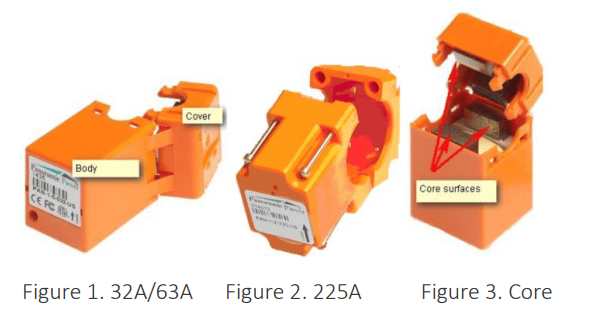
The sensor comes with a label fixed on it, containing a unique ID.
Installing a sensor
- Physically attaching the sensors to the circuit wires;
- Registering the installation in Panoramic Power System.
- Open the cover of the electrical panel board.
- Make sure you have a plan that indicates the circuits to be monitored and the sensor IDs associates with each such circuit. Identify the circuit breaker on which you would like to install the sensor. The ID appears on the label fixed to the sensor.
- Pick a sensor and slide the opener into position from the labeled side towards the cover.
- Snap the opener's pins into the four holes (in 225A unscrew the cover).
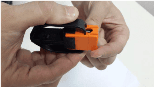
Figure 4. Slide opener into position
5. Press the two sides of the opener to release the sensor cover.
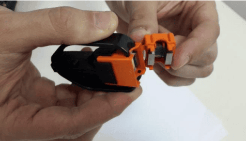
Figure 5. Press the opener to release the cover.
6. Open the four screws.
7. Make sure the four core surfaces are free of dust or any other particles. If necessary, wipe it with a dry cloth.
Note Whenever possible, avoid installing the sensor behind wires and position it at the front of the panel board.
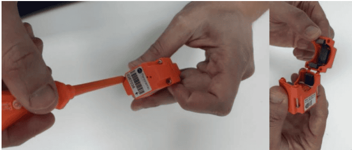
8. Place the opening of the sensor on a clean section of the electrical cable with the arrow on the label pointing towards the load, so that the sensor ID and barcode are visible and easily readable.
9. Close the sensor cover, snapping it into its place (in 225A screw back the cover) and making sure that all four pins are properly inserted and the sensor is tightly closed.
Registering the installed sensor
Visit our Knowledge Base Center to read our articles about mapping the sensors to the devices configured to the site.
Post installation troubleshooting
If the sensor vibrates after installation (you can hear the vibration noise or feel it when touching the sensor), it means that the sensor is not properly closed. Try to press the two parts of the sensor or tighten the screws to close it tightly. If the vibration persists, open the sensor and reinstall it or try using another sensor.
Monitoring sensor activity
Visit our Knowledge Base Center to learn more about the sensor summary window that helps monitor sensor activity.
Uninstalling a sensor
Open the sensor in the way you first opened it and remove it from the cable.